Leave Your Message
-
Phone
-
E-mail
-
Whatsapp
-
Whatsapp

Selecting an Air Type Busway is not just a matter of matching a catalogue rating to a load schedule. The route, fault level, ambient temperature, enclosure rating, and installation space all shape the right choice. A long corridor with frequent tap-off points calls for different considerations than a compact plant room. So does a system expected to expand. Small details matter: a tight bend, a low ceiling, or limited access for bolted joints can complicate installation and future maintenance.
The available material does not identify a verifiable Air Type Busway specialist or provide a sourced quotation. Rather than assign invented words to a named expert, consider this practical design maxim: “Choose for the real load, the actual route, and the maintenance access.” Keep it visible during selection. Compare conductor material, rated current, short-circuit withstand, joint design, and environmental protection against project documents and manufacturer data. Ask the supplier to confirm compatibility with the intended installation and accessories. A catalogue number alone is not enough.
There is no universal best option. One project may value compact dimensions; another may need easier access for inspection. Recheck the assumptions before procurement. Even experienced teams miss constraints when drawings change late. A careful review can prevent awkward site modifications and help the busway serve reliably over time.
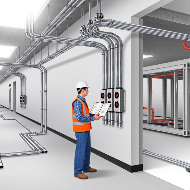
An air-type busway carries electrical power through conductors separated by air and supported by insulated blocks inside a metal enclosure. Its ventilated design can help release heat and allows technicians to inspect joints and connections. That access is useful. It also means the installation environment matters: dust, moisture, or corrosive vapors may call for a more protective enclosure or another distribution method.
These systems are commonly used in factories, warehouses, and large commercial buildings where power must travel along a defined route. A busway above a production line, for example, can provide tap-off points near equipment without running a separate feeder to every machine. Designers should check the available space, support locations, clearance from other services, and how loads may change. Small layout details can become expensive to correct later.
Selection starts with the required current and voltage, but those figures are not the whole story. Fault-current withstand, ambient temperature, installation orientation, and connection requirements also affect suitability. Compare the project conditions with the busway’s published ratings, and have a qualified electrical professional verify the design. Air-type systems are not automatically the simplest choice; an exposed route may be easy to inspect, yet harder to keep clean. Even a careful plan can miss a future equipment move.
| Selection Factor | What to Check | Practical Guidance | Typical Applications |
|---|---|---|---|
| Air-type design | Confirm how the conductors are insulated, supported, and separated inside the enclosure. | Air-insulated busway uses air as part of the insulation system, with supports and clearances designed for the rated voltage. Do not assume every air-type product has the same construction or enclosure arrangement. | Indoor power distribution in commercial, institutional, and industrial buildings. |
| Current rating | Determine the calculated load, expected demand, future expansion, and any applicable design margin. | Select a rating that meets the project load under the manufacturer’s stated installation conditions. Account for ambient temperature, installation layout, grouping, and other derating factors where applicable. | Main feeders, risers, and distribution routes serving multiple loads. |
| Conductor material | Compare the available copper or aluminum conductor options, including their electrical and mechanical data. | Evaluate the complete assembly rather than material alone. Check rated current, voltage drop, joint design, weight, dimensions, and installation requirements for the selected product. | Both materials may be used in building and industrial distribution; the project’s load and installation requirements determine suitability. |
| Voltage and system configuration | Verify system voltage, frequency, number of phases, neutral requirements, and protective-earth arrangement. | Match the busway configuration to the electrical system and connected loads. Confirm that ratings and clearances are appropriate for the project’s operating voltage. | Three-phase building services, industrial distribution, and other systems supported by the selected assembly. |
| Short-circuit withstand | Compare the busway’s short-time withstand and peak withstand ratings with the available fault current at its point of installation. | Coordinate the assembly rating with the upstream protective device and the electrical system study. Verify the manufacturer’s stated test conditions and protection requirements. | All installations, especially main distribution paths supplied by high-capacity transformers or generators. |
| Tap-off and load access | Check whether the design supports tap-off units, their permitted positions, and the required protection and interlocking features. | Plan tap-off locations around the load layout and installation clearances. Confirm that each tap-off unit is rated and protected for its intended circuit. | Factories, offices, and commercial buildings where loads are distributed along a route and may change over time. |
| Route and installation conditions | Review route length, bends, risers, supports, ceiling or shaft space, access for joints, and expansion requirements. | Use the approved layout and installation instructions to coordinate supports, joints, clearances, and any required expansion provisions. Confirm that the route can be installed and maintained safely. | Vertical risers, plant rooms, service corridors, and overhead distribution routes. |
| Environmental protection | Check the enclosure rating and suitability for dust, moisture, temperature, corrosion, and indoor or outdoor exposure. | Air-type construction alone does not establish environmental protection. Select an enclosure suitable for the actual location; seek a different design or additional protection where the environment requires it. | Typically suited to appropriate indoor locations; outdoor, wet, dusty, or corrosive areas require specific product approval and protection. |
| Voltage drop and energy losses | Review manufacturer data for resistance, reactance, impedance, and voltage drop at the expected load. | Evaluate the complete route, conductor size, operating current, power factor, and load profile. Confirm the result against the project’s voltage-drop limits. | Long feeder runs, high-load distribution, and routes supplying sensitive equipment. |
| Standards and verification | Check applicable local regulations and the assembly’s certification or test documentation. | Depending on the market, relevant standards may include IEC 61439-6 or UL 857. Confirm the applicable edition, required approvals, and project specifications with the electrical designer and authority having jurisdiction. | Every project; requirements vary by country, installation type, and approving authority. |