2026 Top Busbar Distribution Systems for Global Buyers
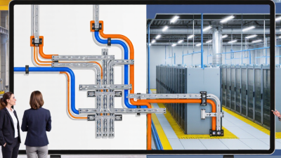
Busbar Distribution systems are becoming a practical choice for facilities that need flexible power distribution and room to expand. Instead of routing every circuit through fixed cable runs, a busway can carry power along a defined path, with compatible tap-off units serving equipment nearby. Details matter. For global buyers, the right choice depends on more than current rating. Copper or aluminum conductors, enclosure protection, short-circuit performance, installation conditions, and future load changes all affect suitability. A system that works well in a clean factory may need different protection in a dusty plant or humid building.
This 2026 guide compares leading busbar distribution options through the details buyers can verify: published electrical ratings, modular configurations, safety documentation, supplier experience, and local technical support. It also considers installation access, maintenance needs, lead times, and compatibility with existing infrastructure. Fit comes first. Product claims should be checked against technical documents and the requirements of the destination market, since certifications and project conditions can differ. Supplier information is not always presented consistently, and that makes direct comparison imperfect. Buyers should confirm unclear specifications before committing, especially where expansion plans or unusual environmental conditions are involved. The goal is not to name one universal winner, but to help purchasers build a reliable shortlist and ask more precise questions. A careful review can reduce avoidable design changes, though it cannot replace qualified engineering assessment for a specific project.
What Busbar Distribution Systems Are and How They Are Used
2026 Top Busbar Distribution Systems for Global Buyers
A busbar distribution system carries electrical power through rigid metal conductors housed inside an enclosure. Instead of running separate cables to every circuit, installers connect equipment to the busbar using compatible tap-off units. The arrangement can supply lighting, motors, production lines, or data-room equipment. It is often used where loads may shift or expand. A factory floor, for example, may need a new machine connection without rebuilding an entire cable route. Busbar systems still require careful sizing; compact layouts do not remove the need to assess heat, current, and fault conditions.
Tips: Check rated current, enclosure protection, and available tap-off positions. Match the system to the installation environment. Ask a qualified electrical professional to verify the design.
For global buyers, compare system ratings and documentation, not appearance alone. Confirm that the busbar, joints, and connection units are designed to work together. Installation space matters: a low ceiling or tight service corridor can complicate access for inspection. Also consider how maintenance will happen after commissioning. Can a section be isolated safely? Are spare parts and technical documents available locally? These details are easy to overlook during procurement. I have seen neat layouts become awkward when later equipment changes were not considered. Planning for realistic future loads is useful, though forecasts are rarely perfect.
Core Components and How Power Is Distributed
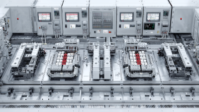
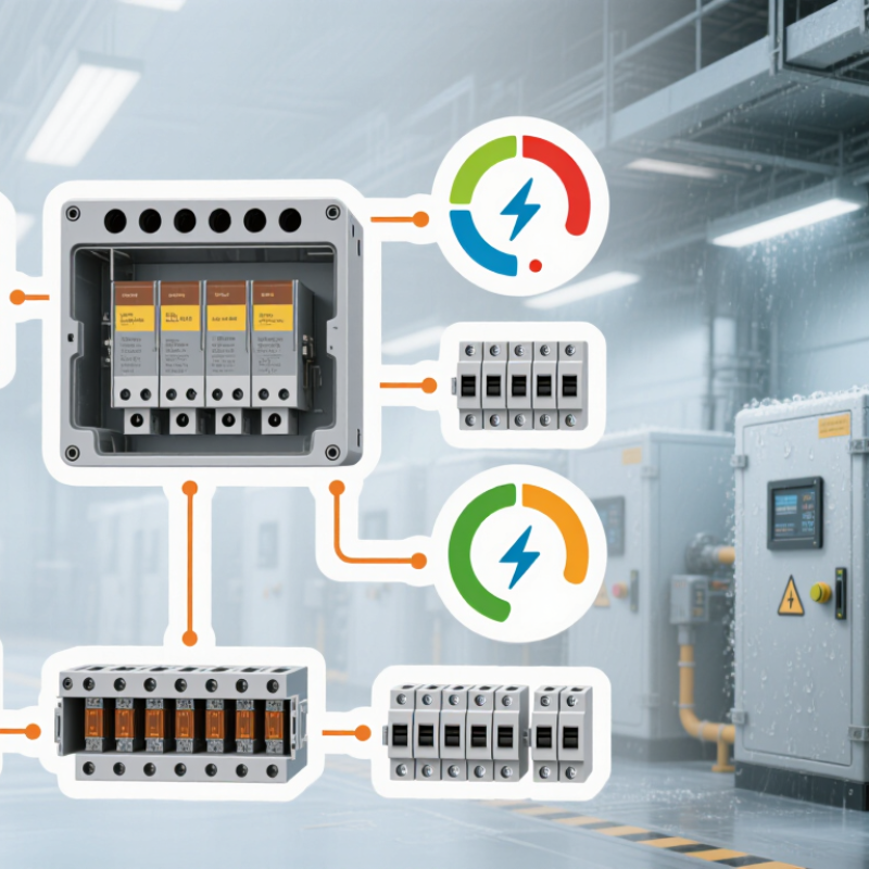
A busbar distribution system carries power from an incoming switchboard to loads through insulated conductors housed in a protective enclosure. Its core parts include feeder sections, straight runs, joints, bends, end feeds, and tap-off units. Breakers or fuses in tap-off units isolate individual circuits, while protective earth maintains a path for fault current. Simple in layout, but details matter. Joint access, correct tightening, and suitable fault ratings affect safe operation. IEC 61439-6 sets requirements for low-voltage busbar trunking systems.
Capacity planning is increasingly important in data centers and industrial facilities. The International Energy Agency’s 2025 Energy and AI report estimates data centers used about 415 TWh of electricity worldwide in 2024, with demand potentially reaching 945 TWh by 2030. That growth puts pressure on distribution capacity and maintenance access. Designers should check load profiles, ambient temperature, enclosure conditions, and future tap-off needs—not just the nameplate current. Heat can build up in crowded routes. And upgrades are not always easy. A careful design leaves room for inspection and expansion, although predicting future loads remains an imperfect exercise.
2026 Top Busbar Distribution Systems for Global Buyers
Core Components and How Power Is Distributed: conductor material comparison
Busbar systems use conductive bars to carry power from an incoming supply to outgoing circuits through tap-off units or breakers. At 20°C, copper has higher electrical conductivity than aluminum. These approximate material values do not determine a system’s current rating on their own; dimensions, temperature rise, enclosure design, and installation conditions also matter.
Main Busbar System Types and Their Applications
Busbar distribution systems are selected by how power must flow, how much downtime is acceptable, and how much space is available. A single-busbar system is straightforward and economical. It suits small commercial buildings, workshops, and facilities with simple loads. However, a fault or planned maintenance can interrupt connected circuits. Simple does not mean suitable for every site.
Sectionalized busbars divide the lineup into sections, often linked by a bus coupler. Operators can isolate one section while keeping other loads energized, which helps in hospitals, factories, and data facilities. Double-busbar systems offer more switching flexibility for substations and large industrial sites, but they need more equipment, space, and operating discipline. Ring busbar arrangements can support continuity around a loop, though protection and switching plans require careful coordination. The neatest drawing is not always the easiest system to operate.
Tips: Match the arrangement to the actual load profile and maintenance plan. Check fault levels, expansion needs, enclosure rating, and heat rise with qualified electrical engineers. Leave clear access around joints and inspection points; cramped layouts can make routine checks harder. Document switching steps, too. Small details matter.
How to Compare Leading Busbar Systems in 2026
For global buyers, comparing busbar distribution systems means checking more than rated current. Match the system’s continuous current and short-circuit withstand rating to the site’s load profile and available fault level. A crowded plant room may need compact trunking, while a dusty production area may require a suitable enclosure rating. Check temperature-rise data, conductor material, joint design, and installation clearances. Details matter.
Compare how each system handles future changes. Removable tap-off units can simplify adding equipment, but only when their ratings and placement suit the actual layout. Review technical drawings, test documentation, maintenance access, and the standards required in the destination market. Ask suppliers how they verify joint integrity and manage installation tolerances. A polished datasheet is useful, but it cannot replace a site-specific engineering review. I have seen comparisons overlook cable-entry space; it is an easy detail to miss.
Tips: Put load, fault level, environment, and expansion plans in one comparison sheet. Request evidence for each rating. Have a qualified electrical engineer review shortlisted systems before purchase. Check the assumptions twice.
Global Standards, Installation, and Buyer Considerations
Global buyers should compare busbar distribution systems against local codes, not assume one certificate works everywhere. IEC 61439-6 covers busbar trunking systems; UL 857 applies to busways in relevant North American markets. Check the exact product rating, short-circuit withstand, ingress protection, and temperature limits. The IEA’s Electricity 2024 report projects global electricity demand will grow by an average of 3.4% annually from 2024 to 2026. That trend makes capacity planning important, but it does not replace a site-specific load study.
Installation details often decide long-term reliability. Confirm support spacing, joint access, expansion provisions, and fire-rated treatment where routes cross building compartments. Verify phase sequence and protective-earth continuity, then tighten joints to the specified torque with a calibrated tool. Small details matter. A drawing may look complete yet overlook the turning space above a congested ceiling. Ask installers to record torque values and inspection results before energization; keep those records for later maintenance. Also assess future tap-off locations, spare capacity, ambient temperature, and dust or moisture exposure. One uncomfortable truth: buyers sometimes select by initial cost, then discover that access or expansion is harder than expected. Good comparisons include installation labor and planned shutdowns, not just equipment price.