Leave Your Message

What Is Air Type Busway and How Does It Work?

Air Type Busway is a practical power distribution system designed to move electrical energy through enclosed, ventilated busbars. Instead of pulling many large cables through crowded conduits, engineers install a compact metal housing along walls, ceilings, or production lines. Inside, insulated conductors carry current along a defined route. Plug-in tap-off units then connect equipment at selected points. The arrangement resembles a controlled electrical highway, with access points positioned beside machinery, lighting systems, or data-center racks.

Electrical engineer Alex McEachern offers a useful guiding principle: “Reliable power distribution depends on controlling both current flow and the installation environment.” This idea explains how Air Type Busway works. Air circulates around the conductors, helping release heat during normal operation. The enclosure also provides mechanical protection and keeps the busbars aligned. However, air cooling does not remove every risk. Designers must still consider load diversity, ambient temperature, short-circuit ratings, spacing, and maintenance access.

A well-designed system can simplify expansion. Technicians may add approved tap-off units without rebuilding an entire cable network. That flexibility matters in factories and commercial buildings where equipment changes frequently. Still, installation quality remains decisive. Loose connections, incorrect ratings, or neglected inspections can create heat damage and unexpected outages. This introduction cannot replace project calculations or manufacturer instructions. It should instead establish a careful starting point for understanding Air Type Busway, its operating logic, and the limitations that responsible engineers must examine.
What Is Air Type Busway and How Does It Work?

Air Type Busway: Definition and Core Components

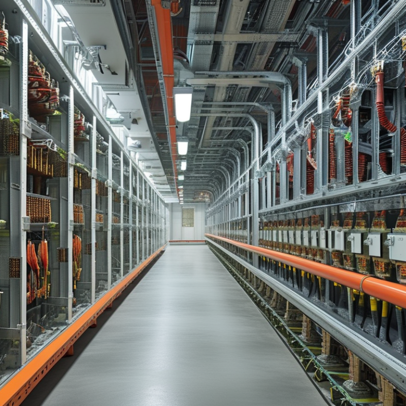
Air type busway is an enclosed power distribution system that uses air as the main insulation medium. Copper or aluminum conductors sit apart inside a metal housing. The air gap reduces contact risk while allowing a compact, flexible layout. Current travels through the conductors, then reaches equipment through tap-off units. It sounds simple. Installation quality decides much of the result.

Core components include phase bars, a neutral bar, a protective earth path, insulating supports, the enclosure, joint covers, and plug-in tap-off boxes. Joint packs connect each section and must maintain electrical continuity.

IEC 61439-6 provides key requirements for low-voltage busbar trunking systems. NFPA 70 also guides installation practices in applicable projects.

The IEA’s Electricity 2024 report estimates that data centers used about 460 TWh globally in 2022. Demand may exceed 1,000 TWh by 2026. That pressure makes scalable busway useful, but capacity calculations cannot rely on market growth alone. Real loads vary.

Tips: Check conductor temperature, fault ratings, enclosure protection, and joint torque before energizing. Leave practical access around tap-off points. Keep phase identification clear. Air is not magic insulation. Dust, moisture, and poor alignment can weaken performance. A commissioning record should include torque checks, insulation tests, and thermal inspection. One design mistake I still see is treating future expansion as guaranteed. Reserve capacity helps, but unused capacity can also increase project cost.
How Air Type Busway Conducts and Distributes Electricity

What Is Air Type Busway and How Does It Work?

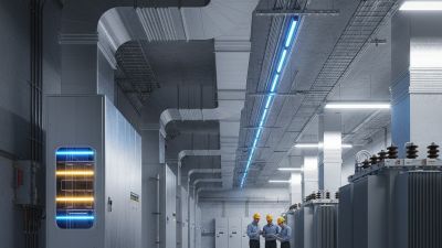
Air type busway uses separate copper or aluminum conductors inside a metal enclosure. Air provides the primary insulation between live conductors and the housing. Electrical current enters through a feeder connection, travels along the busbars, and leaves through plug-in tap-off units. These units supply panels, lighting systems, motors, or server racks without installing a separate cable for every load.

The design is simple, but not casual. IEC 61439-6 requires busbar trunking systems to undergo checks for temperature rise, short-circuit withstand, insulation, and mechanical strength. During operation, heat moves from the conductors to the enclosure and surrounding air. Engineers therefore calculate current capacity, ambient temperature, voltage drop, and available fault current before selecting a section.

A loose joint can create a hot spot. That detail is easy to miss.

The International Energy Agency reported that global data-center electricity use could exceed 1,000 TWh by 2026. This growth increases pressure on flexible distribution systems. Air busway can support that need because tap-off points can be relocated faster than fixed cable circuits. However, flexibility is not automatic. Poor installation, dust, blocked ventilation, or unbalanced loading can reduce performance.

Field inspection still matters. The Uptime Institute’s data-center research also continues to emphasize power resilience and maintenance discipline. In practice, air busway works best when design calculations, torque checks, thermal scanning, and periodic testing remain connected. The equipment is efficient, but it is not self-managing.

Key Installation Steps for Air Type Busway Systems

What Is Air Type Busway and How Does It Work?

Air type busway uses air as insulation between conductors inside a protective metal enclosure. Its open spacing helps manage heat and supports efficient power distribution across industrial and commercial facilities. However, performance depends heavily on careful installation, accurate jointing, and proper clearances.

Key Installation Steps for Air Type Busway Systems

Begin by checking the approved drawings, delivery condition, and installation route. Measure each section before lifting it into position. The first layout is rarely perfect, so small field adjustments may be necessary. Keep the busway clean and dry. Dust, moisture, or dropped hardware can reduce insulation performance.

Install supports at the specified spacing, then align every section without forcing the joints. Misalignment can stress conductors and weaken connections. Join sections with the correct connector assembly, and tighten fasteners using a calibrated torque tool. Record the torque values. This step is often rushed, yet loose connections can create dangerous heat.

Keep power isolated during all connection work. Verify isolation with tested equipment, not assumptions. After assembly, inspect phase identification, enclosure bonding, joint covers, and expansion provisions. Perform insulation resistance and continuity tests before energizing the system. Check phase rotation as well. A final visual inspection should include unusual gaps, sharp edges, and blocked ventilation paths.

Some projects skip a second alignment check. That is a mistake worth reconsidering. Thermal scanning after energization can reveal an overlooked connection problem before it becomes serious. Installation records, test results, and maintenance access should remain available for future technicians.

Performance Benefits and Common Applications

Air Type Busway: Performance Benefits and Common Applications

Air type busway uses air as the primary insulation around enclosed copper or aluminum conductors. Unlike cable trays, it provides a compact, organized path for high-current distribution. From practical installation experience, modular sections can simplify changes when equipment layouts evolve. Joints still deserve careful attention. Proper torque, alignment, and enclosure sealing strongly affect reliability. Air circulation around conductors can help release heat, although site conditions remain important. Ambient temperature, clearances, and load diversity influence actual performance. The results are useful, but not magical.

Common applications include manufacturing plants, commercial towers, data centers, and infrastructure buildings. Busway can connect transformers to switchboards, feed large equipment, or distribute power across production floors. It suits projects requiring frequent tap-off points and future capacity changes. However, it may perform poorly where dust, moisture, or corrosive conditions remain uncontrolled. Engineers should verify short-circuit ratings, enclosure protection, heat rise, and maintenance access before selection. A small design shortcut can become expensive later. Careful review is worthwhile.

Tips: Measure the route twice. Check support spacing and joint access before delivery. Use qualified personnel for installation and testing. Record torque values and inspection results. Do not assume every section performs equally under continuous heavy loads. A site review may reveal that conventional cabling fits better.

What Is Air-Type Busway and How Does It Work?

Air-type busway uses separated, insulated conductors inside a ventilated metal enclosure to distribute electrical power. The chart shows representative continuous-current ratings commonly selected for different application types.

Representative ratings are shown for comparison only. Actual busway selection depends on load demand, voltage, fault-current withstand, ambient conditions, installation method, and applicable electrical codes.

Safety Standards, Maintenance, and System Limitations

What Is Air Type Busway and How Does It Work?

Air type busway uses spaced conductors inside a metal enclosure. Air provides insulation, while the enclosure supports mechanical protection and grounding continuity. Sections connect through joints, allowing power distribution across factories, commercial buildings, and data centers. Its modular design can reduce installation time, but every joint remains a critical point.

Safety depends on correct design and installation.

IEC 61439-6 requires busbar trunking systems to meet verified temperature-rise, short-circuit, insulation, and mechanical performance requirements. In the United States, NFPA 70 requires suitable overcurrent protection, clearances, grounding, and accessible maintenance areas. Installers should inspect joint torque, conductor alignment, enclosure bonding, and signs of overheating. Small gaps matter. Infrared scanning can reveal abnormal heating before visible damage appears.

Maintenance records should include load readings, thermal images, cleaning dates, and joint inspections. Uptime Institute’s 2024 Global Data Center Survey reported that 54% of respondents experienced an outage costing more than $100,000. Poorly maintained distribution equipment can increase that exposure. Air type busway also has limitations. Dust, moisture, corrosive gases, and poor ventilation can reduce insulation reliability. It may require more clearance than compact insulated systems. High fault currents demand careful coordination with protective devices. The “maintenance-free” assumption is risky. In practice, access restrictions, rushed inspections, and incomplete records still create weak points. A qualified engineer should review the installation whenever loads, ambient conditions, or operating patterns change.