Leave Your Message

Why Choose Busbar Busduct for Power Distribution?

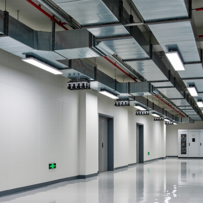
In a commercial building, power must travel safely from the main switchboard to floors, equipment, and work areas. Busbar Busduct offers an enclosed route for conductors, with sections joined along a planned path. Instead of pulling separate cables through long runs of conduit, installers connect busduct sections and position tap-off units where power is needed. That can make distribution easier to adapt when layouts change. It can also keep conductors organized above corridors or inside service spaces. The details matter: load demand, route length, fault levels, environmental conditions, and future expansion all affect the design.

For facility teams, access is part of the decision. A well-planned system can make inspection and connection points easier to identify, while clear labeling supports safer maintenance. Still, performance depends on correct selection, installation, and routine checks. A poorly planned route can create awkward access or leave too little capacity for later growth. Not always. Busduct is not automatically the best choice for every project; cable systems may suit some routes, budgets, or site conditions better. Engineers should compare lifecycle cost, space, installation needs, and applicable electrical requirements before specifying a system. The choice is practical, not merely about appearance. When the route is suitable and the design is verified, Busbar Busduct can provide a structured, scalable approach to power distribution. It deserves consideration, but also careful review.
Why Choose Busbar Busduct for Power Distribution?

What Is Busbar Busduct and How Is It Structured?

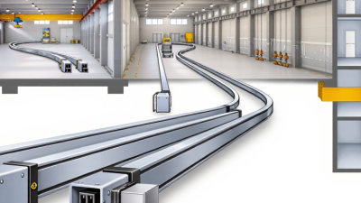
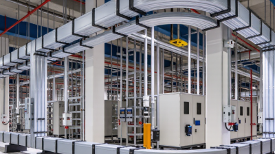
A busbar busduct is a prefabricated electrical distribution system that carries power through enclosed conductors. Unlike loose cables, it uses rigid copper or aluminum bars arranged inside a protective housing. The enclosure may be steel or aluminum, with insulation separating each phase and reducing accidental contact. In practice, sections connect along a planned route, such as above a factory floor or through a service corridor. The result is a defined path. Its capacity, voltage rating, and short-circuit withstand must match the installation and applicable engineering requirements.

A typical run includes straight lengths, elbows, tees, end feeds, and joint packs. At each joint, connectors bridge adjoining bars, while covers and fasteners help maintain alignment and enclosure continuity. Supports hold the duct at specified intervals and allow for building movement or thermal expansion. Tap-off boxes connect branch circuits where needed; their protective devices must suit the connected load. Grounding is essential. Depending on the design, the housing may provide a protective-earth path, but this must be verified. Busduct can simplify access and future changes, though installation is not automatically easier. Heavy sections require careful lifting, and poorly assembled joints can overheat. Small details matter.
How Does Busbar Busduct Distribute Electrical Power?

A busbar busduct distributes electrical power through solid copper or aluminum bars housed inside a protective enclosure. Power enters at a connection point, often from a transformer or switchgear. The conductors carry current along the route, while insulation and supports keep the bars separated and stable. The enclosure also helps protect them from dust and accidental contact.

At selected points, approved tap-off units connect branch circuits to the busduct. Each unit can feed equipment such as lighting panels, pumps, or production machinery. Its protective device helps interrupt current if a fault occurs. That matters. For example, a facility can add a new machine by placing a tap-off at a suitable section, rather than routing a separate cable all the way back to the main switchboard. The layout still needs careful design; a convenient connection point is not automatically a safe one.

During operation, current creates heat, so engineers check load levels, joint quality, and temperature limits. They also consider voltage drop and available fault current. A loose joint can become a hot spot, even when the system looks tidy from outside. Regular inspection helps reveal discoloration, unusual warmth, or damaged enclosure sections. Busduct routes are often easier to adapt than many individual cables, though crowded spaces can make installation and maintenance less simple than expected.

Why Choose Busbar Busduct for Power Distribution?

Busduct carries power along an enclosed busbar run, with tap-off units supplying individual downstream loads. This illustrative example shows how power can be distributed across four branch loads.

Illustrative values, not product ratings: branch power is calculated from 400 V three-phase supply, 0.90 power factor, and assumed branch currents using P = √3 × V × I × power factor. Actual capacity and protection requirements depend on the installation and engineering design.

Which Design Features Affect Its Performance and Safety?

Busbar busduct performance depends on more than conductor size. Copper or aluminum conductors, their cross-section, and the spacing between phases affect current capacity and heat generation. Engineers should check the rated current against expected loads, ambient temperature, and possible future demand. Oversizing is not automatically safer; it can add cost and complicate installation.

Small details matter. Joint design is one of them. Poorly aligned joints or incorrect bolt torque can increase resistance and create hot spots. During commissioning, thermal scans under representative load can help reveal uneven heating. Enclosure material and ingress protection also matter, especially in dusty or damp areas. Heat needs an exit. Ventilation, enclosure shape, and mounting orientation influence temperature rise, while adequate supports limit movement during faults.

Safety also depends on short-circuit withstand ratings, reliable earthing, and the clearances maintained around the run. Supports must match the manufacturer’s specified spacing and suit the building structure. Long routes may need expansion provisions because conductors and enclosures move as temperatures change. Access for inspection should be planned before ceilings or service panels are closed. This detail is easy to underestimate. Design calculations should be checked against actual site conditions, since drawings rarely capture every obstruction or installation constraint.

Why Choose Busbar Busduct for Power Distribution? Which Design Features Affect Its Performance and Safety?

Design Feature Typical Design Data or Options Effect on Performance Safety and Selection Checks
Conductor material Copper or aluminum conductors are commonly used. Their cross-section and allowable temperature rise determine the achievable current rating. Copper generally offers higher conductivity for a given cross-section; aluminum can reduce conductor weight. Actual system performance depends on the complete assembly design. Check the assembly’s rated current, temperature-rise limits, terminal compatibility, and installation instructions—not material alone.
Rated current Available ratings depend on the product range, conductor configuration, ambient conditions, and installation method. A correctly selected rating supports the expected continuous load and future load changes without excessive heating. Allow for load profile, ambient temperature, grouping, ventilation, and any applicable derating factors. Do not select by conductor size alone.
Short-circuit withstand Specified using short-time withstand current and duration, or a conditional short-circuit rating, as applicable to the assembly. Indicates the assembly’s ability to withstand the thermal and mechanical stresses of a fault for the stated conditions. Coordinate the rating with the prospective fault current and protective-device clearing time at the installation point.
Enclosure and ingress protection Enclosure protection is selected for the environment; IP ratings are classified under IEC 60529. The required rating varies by location. Appropriate protection helps limit the entry of solid objects and water while supporting reliable operation in the intended environment. Confirm the complete installed route—including joints, tap-off units, and end covers—maintains the protection required for the site.
Insulation system Insulation materials and clearances are designed for the assembly’s rated voltage, operating temperature, and environmental conditions. Suitable insulation helps maintain dielectric performance and reduces the risk of leakage or phase-to-phase faults. Check rated voltage, temperature limits, pollution or moisture exposure, and the manufacturer’s installation and inspection requirements.
Joint design Joint assemblies typically use bolted connections and defined tightening procedures; some designs include features to help control clamping pressure. Consistent, low-resistance joints help limit local heating and voltage drop along the run. Follow the specified assembly sequence and torque procedure. Inspect joints as required by the installation and maintenance plan.
Voltage drop and conductor layout Voltage drop depends on current, route length, conductor resistance, reactance, power factor, and system configuration. Short, well-planned routes and suitable conductor sizing can improve voltage regulation and reduce distribution losses. Calculate voltage drop for the actual load and route, including connections and operating conditions.
Thermal expansion and supports Support spacing, fixing points, and expansion provisions are selected for the route length, material, and expected temperature changes. Correct support design helps maintain alignment and accommodates movement as the system heats and cools. Use the specified supports and expansion units where required; coordinate the route with building movement joints.
Tap-off points Plug-in or feeder-style tap-off units may be available, with ratings and protective-device options suited to the system design. Distributed connection points can make it easier to supply loads along a route and adapt the layout. Verify tap-off unit compatibility, current rating, protective-device coordination, correct engagement, and any required interlocking.
Fire and compartmentation Where a busduct route crosses a fire-rated wall or floor, a tested firestop system may be required for that specific penetration. Correct treatment helps preserve the building’s fire compartmentation without obstructing the electrical installation. Use a firestop solution appropriate to the assembly and barrier; follow the tested system details and local building requirements.
Protective earthing and bonding The protective-earth path may use a dedicated conductor, an enclosure path, or a design incorporating both, depending on the system. A continuous, correctly sized path supports fault-current return and operation of protective devices. Confirm continuity across joints and fittings, bonding at connections, and compliance with the applicable electrical code.
Standards and verification Busbar trunking systems are covered by IEC 61439-6; other applicable standards and national requirements depend on the market and project. Design verification helps establish that the assembly meets defined requirements for its intended use. Check the applicable standard, rated characteristics, installation documentation, and project-specific inspection requirements.

Note: Values and configurations are system-specific. Confirm ratings, installation conditions, and protection requirements against the selected assembly documentation and applicable local codes.

What Advantages Does Busbar Busduct Offer Over Cables?

Busbar busduct can make high-capacity power distribution easier to organize than a bundle of cables. Its enclosed conductors follow a defined route, often overhead, leaving floor space clearer around equipment. At a panel or production line, this can reduce cable congestion and make inspection more straightforward. Sections and approved tap-off units also allow planned connection points along the run. Less clutter.

Compared with individually routed cables, busduct may require fewer on-site terminations and less support hardware, depending on the layout. This can simplify installation in long, repeatable routes. Its compact profile can also help where trays are crowded. But it is not automatically the better choice. Irregular routes, tight bends, or changing loads may favor cables. Busduct still needs correct ratings, protection, supports, and thermal clearances. Poor planning can erase its advantages.

Tips: Check load, fault levels, route length, ambient temperature, and future connection needs before specifying a system. Leave practical access for maintenance, and verify installation details against the manufacturer’s technical documentation. A site survey helps catch awkward turns and obstructions early. Small details matter. Both options need sound engineering; the best fit depends on the building and operating conditions.

Where Is Busbar Busduct Used, and How Should It Be Selected?

Busbar busduct is used where electrical power must move through a building in a compact, organized route. Common settings include factories, data centers, commercial towers, and large workshops. In a plant, a busduct run may cross above production lines, with tap-off points feeding machines along the way. Space matters. Compared with many parallel cables, a busway can simplify routing, but it still needs room for joints, supports, and maintenance access.

Selection starts with the load. Confirm the system voltage, continuous current, and prospective short-circuit level with a qualified electrical professional. Then check the route: its length, bends, vertical sections, and nearby heat sources all affect the design. An indoor corridor has different needs from a damp service area or a location exposed to dust. Enclosure rating, conductor material, insulation, fire performance, and applicable local standards should match the site conditions.

Plan for how power will change over time. If equipment may be added, accessible tap-off points can help, provided they are rated and positioned for the expected loads. Check voltage drop, temperature rise, fault withstand, and support spacing against manufacturer data and project calculations. A tidy drawing can still miss a cramped joint near a beam. I would not choose busduct on compactness alone; installation cost, shutdown access, and future alterations matter too. Regretfully, those details are often reviewed late.