How to Choose the Right Compact Busway?
Choosing a Compact Busway is not just a matter of fitting power equipment into a narrow space. The right system must match the building’s electrical demand, available routes, and plans for future changes. A busway that looks suitable on a drawing may be difficult to install around beams, pipes, or crowded service areas.
Start by confirming the required current rating, voltage, fault withstand, and protection requirements with a qualified electrical professional. Then compare conductor material, enclosure rating, joint design, and available tap-off units. These details affect performance, maintenance access, and how easily loads can be added or moved. Small details matter. A few centimetres of clearance can change the installation plan.
The site matters too. Check whether the route passes through damp, dusty, hot, or exposed areas, and verify that the product is rated for those conditions. Review manufacturer documentation, applicable project standards, and installation instructions rather than relying on product descriptions alone. Ask about lead times, compatible accessories, inspection access, and support after installation. Real sites are rarely tidy. Even a well-planned route may meet an unexpected obstruction, so some flexibility is worth considering. There is no single best Compact Busway for every project; the practical choice balances electrical capacity, space, safety, expansion needs, and total installation cost.
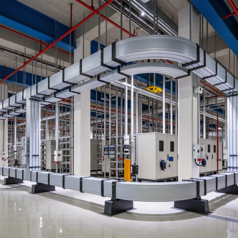
Compare Compact Busway Systems Under IEC 61439-6 and UL 857
Choosing a compact busway means comparing verified performance, not just cabinet size.
IEC 61439-6 addresses low-voltage busbar trunking systems as complete assemblies. UL 857 covers busways in the North American framework. Their test and certification routes differ, so a rating under one standard does not automatically prove compliance with the other.
Check the evidence. Ask for the exact standard edition, test documentation, and certification scope. Then compare rated current, voltage, short-circuit withstand, temperature rise, and enclosure protection. These figures matter in a crowded electrical room, where warm air, tight clearances, and frequent tap-off changes can affect real operating conditions. Review joint design and tap-off hardware, too. A compact housing is useful only if installation and maintenance remain practical.
Not just the label. Confirm that the proposed system’s configuration matches the evidence: conductor material, housing, joint packs, fittings, and tap-off units may influence the tested assembly. Also check project requirements and local authority expectations before selecting a standard. Some documents look clear until an accessory changes. That detail is easy to miss. Compare like-for-like test conditions, and ask a qualified electrical professional to resolve gaps between specifications and site needs.
Calculate Load Capacity Using NEC 215.2’s 125% Continuous-Load Rule
How to Choose the Right Compact Busway?
For a feeder supplying a compact busway, NEC 215.2 generally requires conductor ampacity of at least 125% of the continuous load, plus the noncontinuous load. A continuous load is one expected to run at maximum current for three hours or more. Small loads add up. List the connected equipment, then separate loads by operating pattern before choosing a rating.
For example, an 80-amp continuous load requires 100 amps of ampacity. Add a 40-amp noncontinuous load, and the feeder calculation reaches 140 amps before any applicable adjustment or correction factors. That figure is not automatically the busway size. Check the busway’s marked rating, installation conditions, overcurrent protection, and all applicable code requirements. The adopted NEC edition and local authority can affect the final design. I would not rely on a quick estimate alone; real operating schedules can be less tidy than a load list suggests.
Tips: Check the nameplate. Confirm continuous-load assumptions with measured or documented operating data, and have a qualified electrical professional verify the calculation and equipment selection.
Compare Copper and Aluminum by Ampacity and Voltage-Drop Data
How to Choose the Right Compact Busway?
Compare copper and aluminum using the same current, route length, and installation conditions. The International Annealed Copper Standard (IACS) sets copper conductivity at 100% IACS; common electrical-grade aluminum is about 61% IACS. For equal conductor dimensions, aluminum therefore has higher resistance and usually greater voltage drop. A simple estimate uses Vdrop = I × R, but real busway performance also depends on conductor geometry, joints, temperature, and AC reactance.
Ampacity is not a material-only number. IEC 61439-6 covers busbar trunking systems, while rated current depends on the tested assembly and its operating conditions. Compare each option’s published ampacity and voltage-drop figures at your expected load and route length. For example, a long run serving a steady motor load may make voltage drop more important than a small difference in purchase weight. Check ambient temperature and installation orientation, too. Small details matter.
Tips: Ask for voltage drop in mV/A/m, then calculate the full-run drop at design current. Verify whether the figures assume a particular temperature or enclosure arrangement. Copper can reduce resistance for a given size, but aluminum may still meet the design target with suitable sizing. I would not choose from ampacity alone; that shortcut is tempting, and sometimes wrong.
Verify Short-Circuit Withstand Rating Icw and Protection Coordination
Compact busway selection depends on more than its width or ampacity. Compact dimensions do not reduce fault energy. Check the prospective short-circuit current at the installation point, not only the switchboard rating. IEC 61439-6 covers busbar trunking systems, while IEC 60909 provides methods for calculating short-circuit currents. Use the project’s short-circuit study to confirm the available fault current and the protection device’s clearing time.
For example, a calculated 38 kA fault requires a busway rating that safely withstands the actual current and duration. Check the stated Icw value, such as 40 kA for one second, against the study and manufacturer’s verified data.
Protection coordination matters just as much. Compare the breaker’s time-current curve with the busway’s Icw duration, and check peak withstand current Ipk and the device’s let-through energy. A breaker that clears quickly can reduce thermal stress, but its peak let-through current may still challenge busbar supports. Review the full protective-device settings, including instantaneous trip, rather than relying on a nominal rating. A tidy spreadsheet can hide assumptions about cable length or transformer impedance. That deserves a second look. Record the study conditions, selected protection settings, and the source of each rating in the design file; field conditions may differ from the first calculation.
Choose Enclosure Protection: IEC 60529 IP54 Limits Dust and Water Splashing
Compact busway can run through plant rooms, workshops, and service corridors where dust and occasional splashes are hard to avoid. An IP54 enclosure offers a practical level of protection for these conditions, but the rating has specific limits.
Under IEC 60529, “5” means dust ingress is limited; some dust may enter, but it must not interfere with safe operation. “4” means protection against water splashing from any direction. It does not mean the busway is waterproof. Water jets, flooding, or immersion require a different assessment. That distinction matters near washdown areas. A nearby hose can exceed the protection an IP54 rating describes.
Check the full busway assembly rating, including joints, covers, and connection points. A well-rated enclosure can still be compromised by poorly sealed openings or damaged covers. Look at the route, too: a pipe above the busway may drip onto one joint repeatedly, even when the room seems dry. Small details matter. Ask the supplier for installation and maintenance guidance, and confirm the rating suits the actual exposure. Real sites are messier than drawings. Revisit the choice if cleaning methods or surrounding equipment change.
How to Choose the Right Compact Busway? - Choose Enclosure Protection: IEC 60529 IP54 Limits Dust and Water Splashing
| Selection Factor |
IP54 Meaning or Check |
Practical Guidance for Compact Busway |
| First digit: dust protection |
5 means dust-protected. Dust ingress is not completely prevented, but any ingress must not be sufficient to interfere with satisfactory operation or safety. |
Consider IP54 where airborne dust is present but conditions do not require a dust-tight enclosure. For heavy or persistent dust, assess whether a higher first digit, such as 6, is appropriate. |
| Second digit: water protection |
4 means protection against splashing water from any direction under the IEC 60529 test conditions. |
IP54 can suit locations exposed to occasional splashing, but it does not indicate protection against water jets, flooding, or immersion. |
| Indoor electrical room |
Usually exposed to limited dust and incidental splashes rather than direct washdown. |
IP54 may be suitable when the installed environment matches these conditions and the busway manufacturer confirms the rating for the selected assembly. |
| Production or service area |
Dust levels and water exposure can vary with processes, cleaning methods, and nearby equipment. |
Check for washdown, hose cleaning, conductive dust, oils, and chemical exposure. IP54 alone does not establish resistance to these additional hazards. |
| Outdoor or humid location |
IP54 addresses specified ingress tests; it does not by itself define resistance to UV exposure, corrosion, condensation, or temperature extremes. |
Confirm the enclosure material, corrosion protection, ambient-temperature limits, condensation controls, and any required weather protection separately. |
| Complete installed run |
The protection of a busway system depends on the assembled configuration, not only the straight sections. |
Verify that joints, end closures, tap-off units, covers, and installation details maintain the required protection rating. |
| When a higher rating may be needed |
IP55 adds protection against water jets; IP65 is dust-tight and protected against water jets, subject to the applicable test requirements. |
Select a higher rating only after assessing actual exposure and confirming that the complete busway assembly is tested or declared for that rating. |
Selection note: IP54 means dust-protected and protected against splashing water; it does not mean dust-tight or suitable for high-pressure washing. Check the applicable IEC 60529 classification and the manufacturer’s documentation for the complete installed busway system.