Leave Your Message

Why Choose a Sandwich Bus Duct for Your Project?

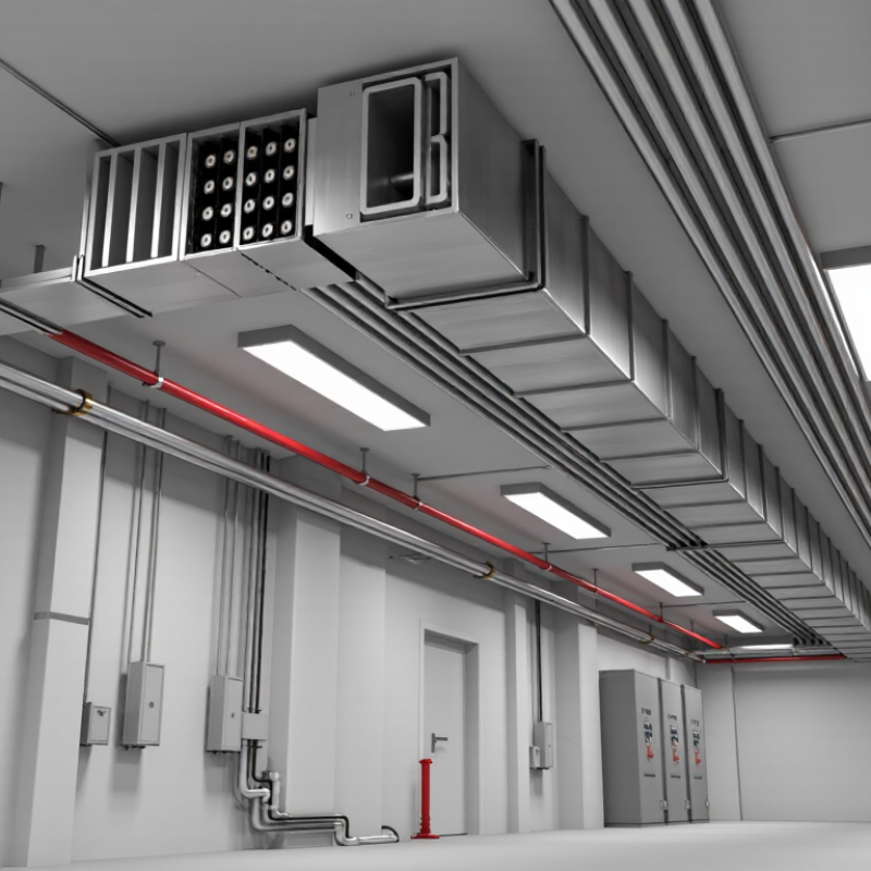
A Sandwich Bus Duct can make power distribution easier to plan in buildings where space, access, and future expansion matter. Its conductors sit within a compact metal enclosure, separated by insulation and joined through purpose-designed connection points. This arrangement can reduce the routing space needed compared with multiple cable runs. Less clutter. Along a plant-room ceiling, for example, a defined bus duct route may leave more room for lighting, pipes, and maintenance access.

The benefits depend on the project, not just the product. Current rating, voltage, fault levels, ambient temperature, enclosure protection, and route length all affect selection. Joint locations matter, too; a poorly planned connection near a beam or equipment panel can complicate installation and later inspection. It depends. A useful design review compares the proposed duct with cable alternatives, checks manufacturer test data, and confirms compatibility with the building’s electrical requirements. Clearances and support spacing should follow the manufacturer’s guidance. So should installation and inspection procedures. A Sandwich Bus Duct may suit a dense commercial floor or industrial line, but it is not automatically the best choice for every route. The practical question is whether its space savings, installation needs, and maintenance access match the site. That deserves a closer look.
Why Choose a Sandwich Bus Duct for Your Project?

What Is a Sandwich Bus Duct?

Why Choose a Sandwich Bus Duct for Your Project?
What Is a Sandwich Bus Duct?

A sandwich bus duct is a prefabricated electrical distribution system. It carries power through flat copper or aluminum conductors held between insulating layers inside a metal enclosure. The compact assembly runs above ceilings, along walls, or through service corridors. Tap-off points let engineers connect equipment where power is needed. Think of a clean metal spine with outlets placed along its route. IEC 61439-6 sets requirements for busbar trunking systems, including construction and verification. The term “sandwich” describes the close, layered arrangement; it does not guarantee a particular capacity or performance.

Why consider it? The U.S. Energy Information Administration reports that transmission and distribution losses averaged about 5% of electricity in the United States from 2018 to 2022. That figure covers the wider grid, not bus ducts specifically. Still, it highlights why sound distribution design matters. A bus duct’s actual losses depend on its rating, conductor material, length, loading, and installation. It is easy to overlook future load growth.

Tips: Confirm the load profile, short-circuit rating, ambient temperature, and available ceiling space before selecting a system. Check access for inspection and tap-off changes, too. A tidy route helps, but poor coordination with sprinklers or cable trays can undo that advantage. EIA data source: “How much electricity is lost in transmission and distribution in the United States?”
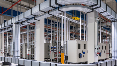
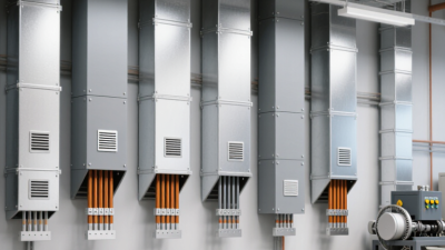
Why Choose a Sandwich Bus Duct? Conductor Material Comparison

Copper has a conductivity of 100% IACS by definition; aluminum is approximately 61% IACS at 20°C. Higher conductivity can help deliver a given current with less conductor cross-sectional area, while aluminum’s lower density can reduce conductor weight. Actual bus duct performance depends on its design, materials, and rated conditions.

How Is a Sandwich Bus Duct Designed and Constructed?

A sandwich bus duct is built around flat copper or aluminum conductors arranged in a compact stack. Thin insulation separates each phase, while an outer metal housing protects the assembly and supports heat transfer. The exact conductor size depends on current, allowable temperature rise, fault forces, and the route length. Details matter. Engineers also consider voltage drop and expansion, since long runs can warm and move under load. A tight layout saves space, but it leaves less room for installation errors.

During construction, conductors are cut, formed, insulated, and assembled into straight sections, elbows, and connection units. Joint packs link sections; their contact surfaces must align cleanly and be tightened to specified values. Small gaps matter. The enclosure usually provides a protective earth path, but bonding continuity must be checked across every joint. Factory testing may include insulation resistance, dielectric withstand, and continuity checks, depending on the design and applicable requirements. On site, installers verify supports, clearances, alignment, and torque records before energizing. Even a well-made duct can underperform if the route was measured poorly. That is an uncomfortable detail, but it belongs in the design conversation.

Why Choose a Sandwich Bus Duct for Your Project? — How Is a Sandwich Bus Duct Designed and Constructed?
Design Dimension Typical Design or Construction Approach Project Data and Practical Checks
System configuration Conductors are closely arranged in a compact stack, separated by solid electrical insulation and enclosed in a metal housing. Specify the number of phases, neutral arrangement, protective-earth path, route, and required tap-off locations before selecting the system.
Conductor material Conductors are commonly made from copper or aluminium. The choice affects weight, conductivity, cost, joint design, and installation handling. Compare complete-system data at the required current rating; do not select by conductor material alone. Confirm compatibility of joints and fittings.
Rated current The manufacturer’s rating is established for a defined product configuration and installation conditions. Determine the design load, diversity, future capacity, ambient temperature, and installation arrangement. Apply any required derating stated in the product documentation.
Insulation system Insulating material separates adjacent conductors and helps maintain electrical clearances in the compact assembly. Verify rated voltage, insulation performance, temperature limits, and suitability for the intended environment using certified product documentation.
Enclosure and ingress protection A metal enclosure provides mechanical protection and forms part of the assembly’s protective-earth arrangement. Select the required IP rating for the installation location. The achievable rating depends on the complete assembly, including joints, end covers, and tap-off units.
Joint construction Sections connect using purpose-designed joint packs or connectors that align conductors and establish electrical continuity. Check the specified joint torque, alignment, access requirements, and inspection procedure. Follow the manufacturer’s installation instructions.
Short-circuit withstand Conductors, joints, supports, and enclosure are designed and verified to withstand specified short-circuit stresses. Coordinate the assembly’s rated short-time and peak withstand values with the available fault current and protective-device clearing characteristics.
Thermal performance Conductor size, insulation, enclosure design, and operating conditions affect temperature rise and current-carrying capacity. Confirm rated current and temperature-rise performance for the proposed orientation, ambient conditions, and installation layout.
Route and support spacing Straight sections, bends, offsets, and supports are planned to suit the building structure and electrical route. Coordinate dimensions, support locations, expansion provisions, and clearances with structural and building-services drawings.
Tap-off provisions Tap-off outlets can provide connection points for downstream loads where the selected system is designed to accept them. Confirm outlet positions, tap-off ratings, protective-device requirements, and whether the system permits safe connection or removal under the specified conditions.
Standards and verification Low-voltage busbar trunking systems are addressed by IEC 61439-6; UL 857 applies to busways evaluated for the North American market. Specify the applicable jurisdiction and require evidence of conformity, ratings, and verification for the exact product configuration.
Why choose a sandwich design? The compact arrangement can help reduce route space and simplify distribution along a building compared with some conventional cable layouts. Assess total installed cost, access for maintenance, route complexity, load distribution, and future extension needs against project alternatives.
Engineering note: Ratings and construction details vary by product and installation. Treat this table as a planning guide; use project-specific calculations and the selected system’s certified technical documentation for final design.

What Electrical and Space Requirements Can It Meet?

Why Choose a Sandwich Bus Duct for Your Project?

Electrical requirements start with the load, not the product. A sandwich bus duct can serve dense distribution routes where high current must pass through a compact assembly. Specify rated current, operating voltage, temperature rise, short-circuit withstand, and tap-off protection against the project’s actual conditions. The IEC 61439-6 standard covers busbar trunking systems, including verification requirements. Still, a standard rating alone does not confirm suitability for a specific installation. Ambient heat, grouping, and future load growth matter.

Demand is rising in power-intensive facilities. The U.S. Department of Energy’s 2024 data center report estimates that U.S. data centers used 176 TWh in 2023, about 4.4% of national electricity consumption. It projects 325–580 TWh by 2028. That is not a bus-duct sizing formula. It does show why expandable distribution deserves attention. Plan spare capacity carefully; oversized equipment can waste space and money.

Space requirements are just as practical. Measure the full route, including bends, joints, tap-off points, and access for maintenance. A compact, enclosed run can help in crowded plant rooms or along ceiling-level corridors, where cable trays compete for room. But clearances still matter. Check structural supports, fire barriers, heat exposure, and access to protective devices before fixing the route. A tidy drawing can hide an awkward joint above a pipe. Walk the route on site, and revise it when reality disagrees.

How Does It Compare With Other Power Distribution Systems?

Why Choose a Sandwich Bus Duct for Your Project?

How Does It Compare With Other Power Distribution Systems?

Choosing a distribution system means balancing space, access, cost, and future load changes. The IEA’s Electricity 2024 report estimates that data centres, AI, and cryptocurrency used about 460 TWh of electricity in 2022; demand could exceed 1,000 TWh by 2026. That growth makes scalable distribution worth considering, though it does not make bus duct the right fit for every project.

A sandwich bus duct places insulated conductors close together inside a compact enclosure. Compared with cable and conduit, it can provide a defined route and convenient tap-off points for equipment along the run. Cables may be easier to route around obstacles or suit smaller installations, but dense cable runs can complicate access and expansion. Bus duct also needs careful planning for supports, joints, and clearances. It does not automatically reduce electrical losses; actual performance depends on load, conductor sizing, and installation. I would still compare installed costs, not just the product price.

Tips: Map likely load changes before selecting a system. Check fault ratings, access, and clearances with a qualified electrical designer.

What Factors Should Guide Your Project Selection?

Why Choose a Sandwich Bus Duct for Your Project?

What Factors Should Guide Your Project Selection?

Start with the load, not the product dimensions. List present demand, expected expansion, and the largest motor or equipment starting current. Then check rated current, voltage, short-circuit withstand, temperature rise, and enclosure rating against site conditions. A compact run can save floor space, but tight bends and crowded access points may complicate installation or later inspection. Check joint locations against the actual route drawing.

Future demand matters. The International Energy Agency’s Electricity 2024 report projects global electricity demand growth averaging 3.4% annually from 2024 to 2026. That is a broad forecast, not a site load calculation. Still, it supports allowing sensible capacity for expansion instead of sizing only for today’s panel schedule. Confirm the design against applicable installation standards, fault levels, ambient temperature, and the manufacturer’s tested configuration.

Reliability requirements should shape the choice, too. Uptime Institute’s 2024 Annual Outage Analysis reports that 54% of surveyed operators said their most recent significant outage cost more than $100,000. This is data-center survey evidence, not a universal project estimate. For critical loads, assess isolation points, inspection access, and replacement procedures before approving the route. A clean drawing can hide awkward maintenance. Walk the proposed path with installers and operations staff; their comments may expose details the design review missed.