Leave Your Message

How to Choose the Right Compact Busway for Your Project?

Choosing the right Compact Busway begins with the building, not the product brochure. The system must match the project’s electrical load, voltage, route, and planned expansion. A warehouse with long ceiling runs has different needs from a compact production floor with frequent equipment changes. Get these details wrong, and installation can become slower and more costly.

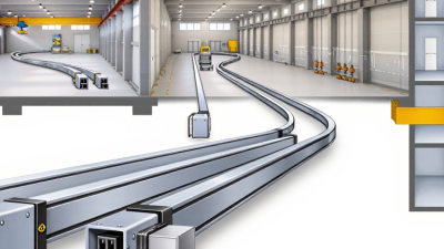
Start by mapping the route and identifying where power needs to reach equipment. Note ceiling height, bends, obstacles, environmental conditions, and available maintenance access. Then compare busway ratings, conductor materials, joint designs, tap-off options, and enclosure protection against the project requirements. Check the manufacturer’s technical documentation, including installation instructions and limits for the selected configuration. Small details matter.

Ask how the system will be installed and inspected. A lightweight section may be easier to handle, but the full route still needs suitable supports and careful joint alignment. Think about future changes, too: adding a machine later may require accessible tap-off points and spare capacity. More capacity is not automatically better; it can add cost without solving a real need.

There is no universal best choice. Project drawings may also miss practical constraints, such as a crowded service corridor or a difficult lifting route. That deserves another look. This guide outlines the key questions for comparing compact busway systems, checking supplier information, and choosing a solution that fits the site. Final selection should be reviewed by qualified electrical professionals against the project’s design requirements.
How to Choose the Right Compact Busway for Your Project?

Define Compact Busway and Its Scope Under IEC 61439-6

A compact busway is a prefabricated, enclosed electrical distribution system designed to carry power through a building with less installation space than many conventional cable arrangements. The word “compact” describes a design, not a separate IEC product class. It has no universal size limit. That label can be vague.

IEC 61439-6:2012 covers busbar trunking systems, including trunking units, fittings, and tap-off units. Its rated-voltage scope is up to 1,000 V AC or 1,500 V DC. Assessment also uses the general requirements of IEC 61439-1. Check the complete assembly’s rated current, short-circuit withstand, temperature-rise performance, and degree of protection. The IEA’s Electricity 2025 report records global electricity-demand growth of 4.3% in 2024. This is useful project context, not a busway sizing rule. Actual selection depends on load, route length, ambient temperature, and future capacity.

Tips: Request the IEC 61439-6 verification documents. Compare tap-off locations and clearance against the real installation route. A neat drawing can still miss a tight ceiling bend.
Calculate Project Load, Diversity, and Required Current Rating

How to Choose the Right Compact Busway for Your Project?

Start with a load schedule, not the sum of every nameplate. List each load’s kW or kVA, voltage, phase, power factor, operating hours, and whether it runs continuously. Then mark which equipment can operate at the same time. A small office may rarely run every heater and charger together; a workshop may run several motors simultaneously. Small loads matter.

The U.S. Energy Information Administration’s 2018 Commercial Buildings Energy Consumption Survey reports 6.8 quadrillion Btu of energy use across U.S. commercial buildings. It tracks heating, cooling, lighting, and equipment separately, illustrating why one blanket diversity factor can mislead. Use project schedules, metering, or equipment sequences to estimate coincident demand. Where operating data is missing, document the assumption.

That is not enough.

For a balanced three-phase system, estimate current with I = kW × 1,000 ÷ (√3 × voltage × power factor). A 150 kW load at 480 V and 0.90 power factor draws about 201 A before applicable adjustments.

Compare that value with the expected peak, not just the daily average. Check continuous-load requirements, ambient temperature, harmonics, and future additions against the applicable electrical code and manufacturer’s rating tables. Even a tidy spreadsheet can be wrong; verify the estimate against actual equipment and site conditions before selecting the busway rating.

Match Voltage, Icw, and Ipk Ratings to System Fault Data

Compact busway selection starts with the electrical conditions at its exact installation point, not only the switchboard rating. Confirm the system voltage, phase arrangement, and insulation level against the project drawings. Then obtain the prospective short-circuit current and the protection device’s clearing time for that location. Small details matter. A feeder near a transformer may face a much higher fault level than a similar run farther downstream.

Icw is the rated short-time withstand current, usually stated with a duration such as one second. Compare it with the calculated RMS fault current, and confirm that upstream protection clears the fault within the tested time. Ipk is the peak withstand current; it addresses the brief mechanical forces created by the first fault-current peak. Check both ratings against verified system studies and the busway’s test data. A matching voltage alone is not enough.

For example, a 400 V installation with high available fault current may need higher Icw and Ipk ratings than the same busway on a long, impedance-limited circuit. Do not assume a breaker’s headline rating proves coordination; its trip curve and let-through performance matter. Estimates can be wrong when transformer impedance or cable lengths change. That assumption deserves a second look. Recheck figures after design revisions, and have a qualified electrical engineer confirm the selection.

Compare Copper or Aluminum Conductors and 3- or 4-Pole Designs

Copper and aluminum busways can carry the same project load, but their size and installation demands differ. Under the International Annealed Copper Standard (IACS), copper is the 100% conductivity reference; electrical-grade aluminum is about 61%. Aluminum usually needs a larger cross-section for comparable current capacity, while its lower weight can ease handling over long ceiling runs. Copper may suit tight risers where space is limited. Check the manufacturer’s tested ratings, joint design, ambient temperature, and expansion requirements—not conductor material alone.

Pole count matters just as much. A 3-pole design typically serves three-phase loads that do not require a neutral conductor. A 4-pole design includes a neutral path, useful for mixed single-phase loads and systems with significant harmonic currents. The IEA’s Electricity 2024 report notes that global electricity demand grew 2.2% in 2023 and forecasts average annual growth of 3.4% through 2026. That broad trend is no substitute for a project load study. It does, however, make future capacity worth checking.

Confirm how the busway connects to transformers, panels, and equipment before choosing. Neutral sizing deserves special attention in offices with many electronic loads. Ask for temperature-rise and short-circuit test data under IEC 61439-6, the standard covering busbar trunking systems. One detail is easy to miss: a lighter aluminum run may still need more installation space. Compare the full route, joints, supports, and maintenance access on site.

Verify IEC 61439-6 or UL 857 Compliance and Installation Clearances

For a compact busway, verify the exact assembly against IEC 61439-6 or UL 857—not just a sales specification. These standards address busway construction, testing, and performance, but they are not interchangeable. Confirm the project’s required certification, voltage, current rating, and fault withstand rating with the electrical engineer. Ask for the test documentation. Check that joints, tap-off units, and supports match the approved configuration.

Installation clearance deserves equal attention. Measure the space around elbows, joints, and access covers on the actual route, including near ceilings, pipework, and cable trays. Leave room to install and inspect connections, and follow the applicable code and installation instructions for ventilation and access. NFPA’s 2022 report on home electrical fires estimated 46,700 fires annually involving electrical failure or malfunction in 2015–2019; these were not busway-specific, but they underline why sound electrical installation matters. A tight drawing can still hide a blocked access cover. Small gap. Big problem. Recheck clearances on site before fixing supports, because a few millimetres can change whether a joint is serviceable.

How to Choose the Right Compact Busway for Your Project? — Verify IEC 61439-6 or UL 857 Compliance and Installation Clearances
Selection Dimension What to Confirm Evidence to Request Project Check
Applicable product standard For busbar trunking systems assessed to IEC requirements, check IEC 61439-6 together with the applicable general requirements of IEC 61439-1. For installations requiring North American product approval, check the applicable edition of UL 857. Product documentation identifying the standard and edition, plus certification or conformity records applicable to the project and jurisdiction. Confirm the required approval route with the project engineer, authority having jurisdiction, and local regulations. Do not treat IEC and UL markings as interchangeable.
Rated operational voltage Check that the busway’s rated voltage is suitable for the system voltage and the intended circuit configuration. Product nameplate and technical data sheet showing rated voltage and system details. Verify compatibility with the supply system, insulation requirements, and connected equipment.
Rated current Select a current rating appropriate to the calculated load and the applicable design rules. Consider ambient temperature, installation arrangement, and any manufacturer-stated derating factors. Current rating, temperature-rise data, and derating instructions from the product documentation. Have the electrical designer confirm the load calculation and any continuous-load or local-code requirements. Do not size from connected load alone.
Short-circuit withstand Check the busway’s declared short-circuit withstand rating and duration against the prospective fault current and protective-device clearing conditions. Short-circuit rating and coordination information for the specified busway configuration. Confirm that the protective device and installation arrangement are consistent with the documented rating.
Conductors and configuration Confirm conductor material, number of conductors, neutral and protective-earth arrangement, and any required tap-off or feeder configuration. Construction details, circuit diagrams, and ordering information for the exact configuration. Check compatibility with the source, loads, earthing system, and planned connection points.
Enclosure and environmental protection Choose an enclosure and ingress-protection level suitable for the location, including exposure to dust, moisture, or washdown where applicable. Declared IP rating or other applicable enclosure classification, together with installation limitations. Match the declared protection to the actual environment; an enclosure rating does not replace requirements for suitable installation and maintenance.
Route, dimensions, and support Check the busway dimensions, joint locations, bend options, support spacing, and the structural capacity of the intended route. Dimensioned layout drawings, installation instructions, support details, and component weights. Coordinate the route with structural elements, lighting, piping, ducts, and access needed for assembly and inspection.
Installation clearances Use the clearance requirements stated in the manufacturer’s installation instructions and applicable electrical codes. Required space can depend on the busway design, joints, tap-off units, and surrounding equipment. Installation manual and project-specific layout showing access, working space, and any required separation from adjacent equipment. There is no single universal clearance value that applies to every compact busway. Verify the actual product instructions and local code requirements before fixing the route.
Expansion, joints, and movement Determine whether the route requires expansion provisions or special treatment at building movement joints, and follow the specified joint assembly sequence. Route design guidance, joint instructions, and any stated limits on run length or movement. Coordinate long runs and building interfaces with the product documentation and the project’s structural design.
Installation and inspection Follow the specified assembly, alignment, torque, earthing, and pre-energization checks for the selected system. Manufacturer’s installation and maintenance instructions, including any required inspection or test records. Use qualified personnel and document inspections and tests as required by the project specification and local regulations.
Spare capacity and future changes Consider expected load growth, available tap-off positions, and whether the selected layout allows practical future extension. System layout, compatible component list, and documented limits for extensions or additional tap-off units. Allow for future needs without exceeding ratings or compromising clearances, access, or protective-device coordination.
Important: Confirm the exact product configuration, applicable standard edition, local approval requirements, and installation clearances before procurement. Ratings and clearances must be verified from the documentation for the specific busway system and project conditions.