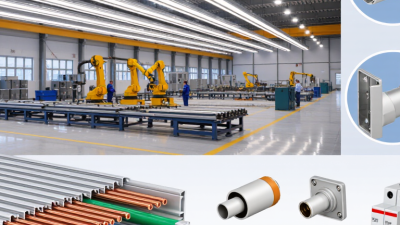
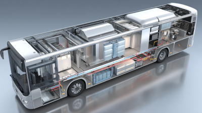
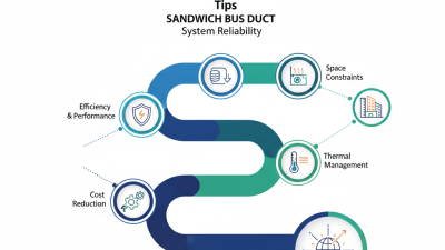
China’s leading Aluminum Dense Busway manufacturers serve projects where electrical capacity, space, and installation time all matter. In factories and data centers, a busway’s compact route can simplify distribution above busy floors. But a polished catalog is not proof of performance. Buyers still need to check rated current, temperature rise, short-circuit withstand, joint design, and enclosure protection.
The International Energy Agency’s Electricity 2024 report projected average global electricity-demand growth of 3.4% annually through 2026. That forecast is broader than the busway market, but it helps explain rising pressure on electrical infrastructure. IEA Executive Director Fatih Birol described the wider shift with the phrase “the Age of Electricity is here.” His comment concerns energy demand, not any specific busway product. That distinction matters.
For China-based suppliers, aluminum conductors can offer lower weight than copper, while performance depends on alloy, cross-section, connection quality, and system design. Ask manufacturers for test reports, technical drawings, installation guidance, and evidence that ratings apply to the complete assembly. Compare like with like. A low quoted price may leave out accessories or support requirements. And site conditions can change the answer. This guide introduces leading manufacturers and practical selection criteria, while recognizing one limitation: public product data rarely makes every factory’s quality equally easy to verify.
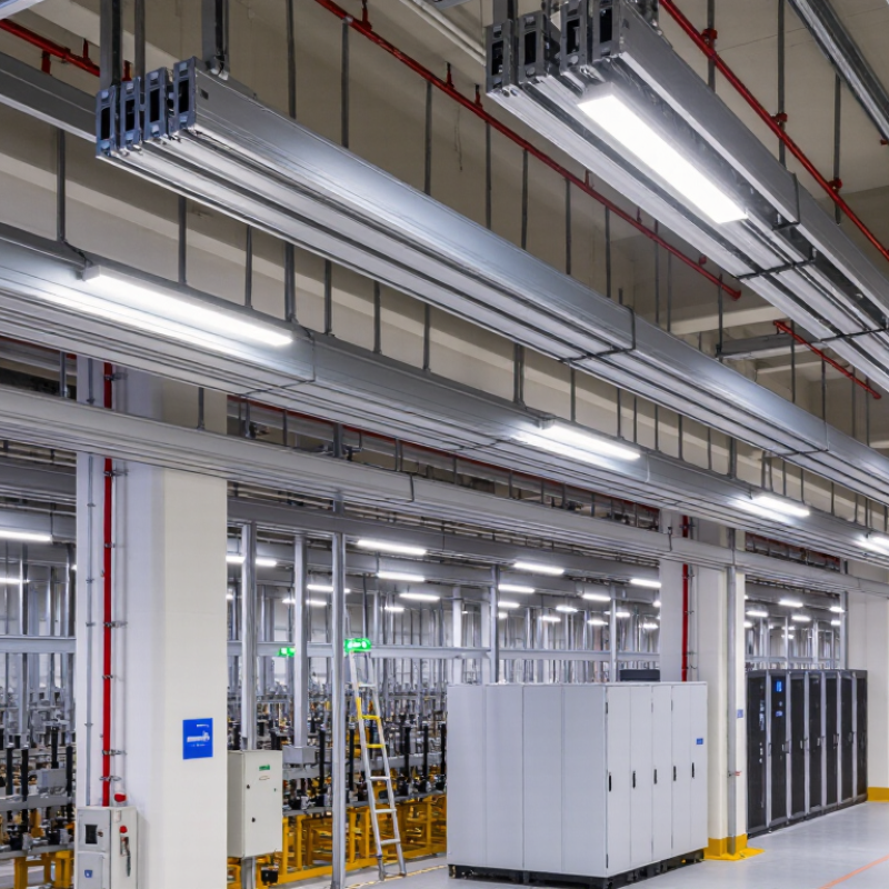
An aluminum dense busway is a compact power-distribution system built from insulated aluminum conductors inside a protective metal housing. Its closely spaced conductors carry electricity through a building, offering an alternative to runs of separate cables. The aluminum core is lighter than a comparable copper conductor, which can make handling and installation easier.
Compact does not mean effortless.
Power enters through a feeder unit and travels along the busway sections. At designated points, tap-off boxes connect equipment such as lighting panels or machinery. Joint packs link sections together, so correct alignment and tightening matter. Small details matter. A loose joint can create heat, while an unsuitable tap-off position may complicate later changes.
In a factory or commercial building, installers may route sections overhead, then add tap-off units near equipment as the layout develops. The system’s ratings, enclosure protection, support spacing, and ambient conditions should match the actual installation. Aluminum also expands with heat, so joint design and installation instructions deserve careful attention. A neat drawing can make the job look simpler than it is; real site conditions often require adjustment.
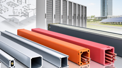
A dense busway combines aluminum conductors, insulation, a protective metal enclosure, joint packs, and access points for power distribution. Each part affects safety and operating performance. The aluminum bars carry current with lower weight than many copper alternatives, while their cross-section must suit the load and installation conditions.
Insulation separates conductors and helps limit electrical leakage. Its temperature rating and condition matter, especially in warm plant rooms or crowded risers. The enclosure protects the bars from impact and dust, and can help dissipate heat. Joint packs connect straight sections; accurate alignment and specified bolt torque help maintain reliable contact. Connections matter.
Tap-off units let equipment draw power at designated points along the route. Their ratings and protective devices should match the connected load. A well-designed system also considers voltage drop, short-circuit withstand, ambient temperature, and future capacity. These figures need verification against project conditions, not assumptions from a product description. Small details count.
During installation, crews should check joint tightness, support spacing, and clear access for inspection. Even a sound busway can underperform if joints are poorly assembled or later additions overload the system. That part is easy to overlook.
China’s aluminum dense busway manufacturing landscape benefits from a large domestic aluminum supply chain. The International Aluminium Institute reported that China produced about 41.5 million tonnes of primary aluminum in 2023, roughly 59% of global output. Supply is substantial. However, this figure does not measure busway-grade production or factory capability. Product quality also depends on extrusion tolerances, conductor design, joint resistance, insulation, and testing.
Manufacturers coordinate profiles, conductors, housings, and plug-in units across regional supply chains. IEC 61439-6 specifies requirements for busbar trunking systems, including temperature-rise and short-circuit verification. Buyers should compare rated current, conductor material, IP rating, joint design, and test documentation—not headline capacity alone. A profile can look precise. A weak joint may still overheat. Public statistics rarely separate aluminum dense busway output from broader electrical equipment, so production claims deserve careful checking.
Tips: Request test reports for the exact configuration. Confirm joint torque instructions and inspect sample joints. Small details matter.
When evaluating Chinese aluminum dense busway manufacturers, compare engineering evidence rather than brochure claims. Request rated-current tables, temperature-rise test reports, and short-circuit test data for the proposed configuration. Check whether the reports match the conductor material, enclosure, and joint design you plan to buy. Details matter.
Ask how the manufacturer controls aluminum conductor dimensions, surface treatment, and connection torque. Request drawings showing joint packs, insulation barriers, and installation clearances. A factory visit can reveal whether inspection records follow each production batch. If visiting is not practical, ask for dated production photos and sample inspection documents. Verify that stated protection ratings and test methods suit your project conditions. No checklist catches everything. Leave room for questions.
Tips: Compare the same specifications across suppliers. Ask who handles commissioning support and replacement parts. Keep one sample joint for inspection; it can expose small differences that a datasheet may miss.
Suggested weighting for a dense busway supplier assessment. These are proposed procurement priorities, not measured market statistics or ratings of specific manufacturers.
Use the criteria as a starting point, then verify applicable certifications, test reports, product ratings, and project requirements during supplier qualification.
Aluminum dense busways are used to distribute power in commercial buildings, factories, and data centers. Their compact profile can serve equipment rows where large cables are difficult to route. They are also relatively light, which can ease handling during overhead installation. That matters. Yet a lighter busway is not automatically the right choice for every feeder.
Selection should start with the expected load, voltage, route length, and available fault current. Check the manufacturer’s ratings for continuous current, temperature rise, and short-circuit withstand. Aluminum connections need careful attention; verify joint design, tightening instructions, and inspection requirements. Heat, dust, moisture, and corrosive air can also affect enclosure and protection choices. A small mismatch here can create costly problems later.
During layout review, confirm clearances, support spacing, expansion provisions, and access for maintenance. A tight ceiling may look manageable on a drawing but prove awkward around lights, pipes, and cable trays. I would compare the complete installed system, not just conductor material or purchase price. No calculation replaces checking site conditions. Leave room for future taps if loads may change, but avoid oversizing without a reason. Some project details are easy to miss, so a qualified electrical designer should verify the final selection against actual operating conditions.
| Application | Typical Current Range | Common Installation Conditions | Key Selection Factors | Relevant Checks |
|---|---|---|---|---|
| Commercial buildings and office towers | 250–1,600 A | Vertical risers and horizontal distribution routes; often installed in electrical shafts or service corridors. | Load demand, floor-tap-off layout, space constraints, fire-stopping requirements, and ease of future expansion. | Confirm rated current, conductor configuration, enclosure protection, joint access, and compatibility with the building’s distribution system. |
| Shopping centers, hotels, and public facilities | 400–2,000 A | Routes may pass through plant rooms, service areas, and spaces with varying ambient temperatures. | Expected diversity of loads, tap-off unit locations, environmental conditions, maintenance access, and required protection against dust or water. | Check the intended IP rating, circuit protection coordination, installation clearances, and the manufacturer’s temperature-rise data. |
| Factories and industrial workshops | 400–3,200 A | Overhead distribution near production equipment; exposure to vibration, dust, heat, or process-related contaminants may occur. | Motor-starting and operating loads, route length, short-circuit withstand, mechanical support spacing, and suitability for the actual environment. | Review prospective fault current, protective-device settings, enclosure material and finish, support design, and applicable IEC 61439-6 test documentation. |
| Data centers and critical power rooms | 800–5,000 A | High-density distribution routes, often with closely planned power paths and restricted installation space. | Continuous load profile, redundancy strategy, voltage drop, fault level, monitoring needs, and access for inspection or replacement. | Verify system configuration, rated operational voltage, short-circuit ratings, joint integrity, thermal performance, and coordination with upstream protection. |
| Warehouses and logistics facilities | 250–1,600 A | Long overhead runs serving lighting, conveyors, charging areas, and distributed equipment. | Route length, number and spacing of outlets, potential future load additions, mounting height, and exposure to dust or accidental impact. | Check voltage drop, tap-off rating, mechanical supports, enclosure protection, and access for safe operation and maintenance. |
| Transportation and infrastructure facilities | 400–3,200 A | Electrical distribution in stations, terminals, utility buildings, and other infrastructure areas. | Environmental conditions, service continuity, installation access, fire-safety design, and coordination with project specifications. | Confirm applicable project and local requirements, system fault ratings, corrosion protection where needed, and tested assembly documentation. |
| Aluminum conductor selection | Selected according to the required system rating | Suitable for busway designs engineered and tested for aluminum conductors. | Compare rated current, conductor dimensions, joint design, thermal performance, weight, and total installed cost; do not select by conductor material alone. | Request rated-current and temperature-rise evidence for the proposed assembly and installation conditions. Aluminum and copper ratings are not interchangeable without design verification. |
| Enclosure protection and environment | Project-specific | Indoor dry areas, dusty spaces, damp locations, or areas requiring greater protection. | Select an enclosure protection level appropriate to the exposure, cleaning method, ventilation, and installation location. | Confirm the declared IP rating applies to the complete installed system, including joints, end feed units, and tap-off points. |
| Electrical and mechanical coordination | Project-specific | All routes, especially long runs, risers, and systems with multiple changes in direction. | Rated voltage, rated current, short-circuit withstand, voltage drop, support arrangement, expansion provisions, and connection to switchgear. | Check the design against the project load schedule and fault study; confirm dimensions, accessories, installation instructions, and IEC 61439-6 documentation. |
| Current ranges are indicative examples for application planning, not guaranteed product ratings. Final selection depends on the complete busway assembly, ambient temperature, installation method, circuit configuration, protection devices, fault level, and applicable project requirements. Confirm all ratings and test documentation with the supplier before specification or installation. | ||||